NOTE: This blog is not about the merits, performance, or lack thereof with dual-5 GHz radios. This is a blog about the operation or dual-cell APs, specifically how the AP transitions clients between the macro and micro cells.
Cisco 2800/3800 APs support Flexible Radio Assignment, which allows the 2.4 GHz radio to flip to either a monitor or another client-serving 5 GHz radio. When the AP is operating in this dual-5 GHz mode, the normal radio (slot 1) powers the macro cell, and the flexible radio (slot 0) powers the micro cell. The terms macro and micro are used for two reasons. When the flexible radio is put into 5 GHz mode, either automatically through the FRA algorithm or manually, the radio switches to a more directional antenna than the normal 2.4 GHz antenna. See the antenna radiation patterns of the 3800 from the AP2800/3800 Deployment Guide:
The second reason is the reduction in power on the flexible radio when operating in dual-5 GHz mode. The flexible radio is locked into transmitting at the lowest power supported, which is usually 2 dBm. The reduction in power, along with a mandatory separation of at least 100 MHz between the micro and macro radios, is to reduce the near-field effects of the two radios interfering with one another.
Looking at the elevation pattern (right), you can see that the macro radio has a "dead spot" directly below the AP. The micro radio (blue line) has a 15 dB advantage over the macro radio in this dead spot. Unfortunately because of the power limit on the micro radio, most clients will still perceive the macro radio as having a higher signal strength. This is even more true when not directly under the AP.
In order to take advantage of the micro cell, the AP/Controller has to have a way to nudge clients that connect to the macro cell over to the micro cell. This mechanism is called client steering, and the default method to steer clients is the 802.11v BSS Transition Request.
To see how client steering works with flexible radios the following settings must be made on the controller:
It's also helpful to see the BSSID values that are assigned to the macro and micro cells, to be able to confirm values in the BSS Transition Management requests.
Note the difference in the last octet of the BSSIDs between the macro and micro cells. I will reference this later.
The command to list the client steering parameters, their default values and explanation are shown below:
Cisco 2800/3800 APs support Flexible Radio Assignment, which allows the 2.4 GHz radio to flip to either a monitor or another client-serving 5 GHz radio. When the AP is operating in this dual-5 GHz mode, the normal radio (slot 1) powers the macro cell, and the flexible radio (slot 0) powers the micro cell. The terms macro and micro are used for two reasons. When the flexible radio is put into 5 GHz mode, either automatically through the FRA algorithm or manually, the radio switches to a more directional antenna than the normal 2.4 GHz antenna. See the antenna radiation patterns of the 3800 from the AP2800/3800 Deployment Guide:
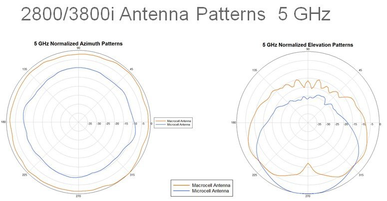 |
| AP3800 Antenna Patterns |
Looking at the elevation pattern (right), you can see that the macro radio has a "dead spot" directly below the AP. The micro radio (blue line) has a 15 dB advantage over the macro radio in this dead spot. Unfortunately because of the power limit on the micro radio, most clients will still perceive the macro radio as having a higher signal strength. This is even more true when not directly under the AP.
In order to take advantage of the micro cell, the AP/Controller has to have a way to nudge clients that connect to the macro cell over to the micro cell. This mechanism is called client steering, and the default method to steer clients is the 802.11v BSS Transition Request.
To see how client steering works with flexible radios the following settings must be made on the controller:
- Flexible Radio Assignment must be enabled globally under Wireless -> Advanced.
- The flexible radio in the AP2800/3800 can either be set to Auto or client serving. When in auto mode, the FRA algorithms determines if it is better to leave the radio in 2.4 GHz client serving mode, monitor mode, or 5 GHz client serving mode. For my testing I manually configured the flexible radio as 5 GHz client serving.
- BSS Transition Management must be enabled for the WLAN that the clients will connect to.
Unlike normal BSS Transition Management between distinct APs, Optimized Roaming is not required for 11v frames to be used to transition clients between the macro and micro cells. Radio power and channel settings can be left to auto. The power will not be adjustable on the micro radio, even if it it set to manual. For ease of testing, I removed DFS channels from the 802.11a channel plan. This is how my AP3800 looked:
AP Name                          Channel    TxPower       Allowed Power Levels
-------------------------------- ---------- ------------- ------------------------
FRA-AP                           44*        *8/8 ( 2 dBm) [22/19/16/13/10/7/4/2]
FRA-AP                           149*       *2/7 (16 dBm) [19/16/13/10/7/4/2/0]
It's also helpful to see the BSSID values that are assigned to the macro and micro cells, to be able to confirm values in the BSS Transition Management requests.
(Cisco Controller) >show ap wlan 802.11a FRA-AP Site Name........................................ TestGroup Site Description.................................WLAN ID Interface BSSID ------- ----------- -------------------------- 14 xxxxxxxxxx 58:ac:78:xx:xx:3f
(Cisco Controller) >show ap wlan 802.11-abgn FRA-AP Site Name........................................ TestGroup Site Description.................................WLAN ID Interface BSSID ------- ----------- -------------------------- 14 xxxxxxxxxx 58:ac:78:xx:xx:30
Note the difference in the last octet of the BSSIDs between the macro and micro cells. I will reference this later.
The command to list the client steering parameters, their default values and explanation are shown below:
(Cisco Controller) >show advanced client-steering

Client Steering Configuration Information

  Macro to micro transition threshold............ -55 dBm
  micro to Macro transition threshold............ -65 dBm
  micro-Macro transition minimum client count.... 3
  micro-Macro transition client balancing win.... 3
  Probe suppression mode......................... disabled
  Probe suppression validity window.............. 100 s
  Probe suppression aggregate window............. 200 ms
  Probe suppression transition aggressiveness.... 3
  Probe suppression hysteresis................... -6 dBm
Macro to micro transition threshold: This is a value in RSSI above which a client can be transitioned from the macro cell to the micro cell. The default is -55 dBm. This is the RSSI at the AP. For example, if a client connects to the macro cell and its RSSI at the AP is greater than -55 dBm, it is a candidate to be transitioned to the micro cell.
Micro to macro transition threshold: This is a value in RSSI below which a client can be transitioned from the micro cell to the macro cell. The default it -65 dBm. For example, if a client connected to the micro cell initially and had a RSSI at the AP of less than -65 dBm, it will be transitioned to the macro cell. Given the power difference between the macro and micro cells, is is rare for clients to be transitioned from the micro cell to the macro cell.
micro-Macro transition minimum client count: The minimum number of clients in either macro or micro cells that will trigger a transition for the next client connecting. The default is 3. For example, if there are 3 clients in the macro cell, the 4th client that tries to connect to the macro cell will be transitioned to the micro cell, if it meets the requirements for macro-to-micro transition threshold RSSI.
micro-Macro transition client balancing window: This specifies the minimum difference in client count between the macro and micro cells that must exist before a client can be transitioned between cells. The default is three. Imagine a scenario where there are 5 clients in the macro cell and 3 in the micro cell. The difference in clients between the cells is 2, which is below the default balancing window value of 3. The next client that connects to the macro cell will not be transitioned to the micro cell, even it it meets the RSSI requirements. Now there are 6 clients in the macro cell and 3 in the micro cell, and the difference in client count now meets the balancing window requirement. The next client that connects to the macro cell will be transitioned to the micro cell, IF it meets the RSSI requirement.
I only had two 802.11v capable clients to test with, so I changed both the transition minimum client count and transition client balancing window to 1.
With these parameters, I could connect one client to the macro cell, and the second client to connect would (hopefully) get transitioned to the micro cell. I used 'debug client' and specified the MAC addresses for both clients.
I connected the first client to the SSID and confirmed through the CLI that it had connected to the macro cell. When using an AP setup in macro/micro, you will see extra lines in the 'debug client' output that contain XOR:
The first client is not eligible for transition to the micro cell because it is the only client in the macro cell. Let's see what happens when the second client connects to the macro cell.
We see in the second line that the debug output shows a RSSI value of 212. I'm not sure how this scale of RSSI equates to a power level in dBm, but it appears to be above the threshold of -55 dBm. The third line indicates that the client will be scheduled for transition.
Before the client is transitioned, it sends a 802.11k Neighbor Report request. The debug output is interesting.
Because the client-steering engine had already decided to transition this client to the micro cell, it limits the list of neighbors it will send back to the BSSIDs on the micro cell.
Note that the transition of the client is scheduled; it doesn't happen immediately. Perhaps this is to prevent flapping of clients transitioning between the micro and macro cells as clients join and leave the cell. It may also be delayed to allow clients in motion to roam to other macro cells, instead of being pulled back into the micro cell of a far away AP. My testing indicates that the amount of time that elapses between the association of the client that triggers the XOR roam and the transmission of the 802.11v BSS Transition Management Request varies. If I find more information I will update this blog.
Below we see the sequence of events as the second client is transitioned to the micro cell.
Line 1 is the debug entry for sending the 11v BSS Transition Request, which is acknowledged in line 4. The client re-associates in line 5. Line 6 indicates that the client is associating to the XOR radio slot 0, which is the micro cell. In line seven we see that the client is not eligible for transition from the micro back to the macro cell: the difference in the number of clients between the cells (0) is not greater than the transition client balancing window (1).
Over the air, we see a BSS Transition Management request that includes a candidate list. The only entry in the candidate list is the BSSID of the WLAN on the micro radio.
Wireshark does not completely decode the candidate list entries, but they are in the same format as an 802.11k Neighbor Report. I highlighted the important elements: the BSSID and the channel number. The BSSID matches what we expect, and so does the channel number, 44. The client responds to the request with the following action frame.
The important fields here are the BSS Transition Response Status Code and the BSS Transition Target BSS. The Status Code communicates whether the client accepts or rejects the request, and a value of 0 indicates that client accepts it. The Transition Target BSS indicates the BSSID that the client intends to transition to. In this case, it matches the BSSID in the candidate list from the request frame.
Now we see that the second client has been transitioned to the micro radio on slot 0.
That's it for Part 1 of this series on client steering between macro/micro cells on an AP3800. Next I will look at what can be done if clients do not support 11v.
(Cisco Controller) >show advanced client-steering

Client Steering Configuration Information

  Macro to micro transition threshold............ -55 dBm
  micro to Macro transition threshold............ -65 dBm
  micro-Macro transition minimum client count.... 1
  micro-Macro transition client balancing win.... 1
I connected the first client to the SSID and confirmed through the CLI that it had connected to the macro cell. When using an AP setup in macro/micro, you will see extra lines in the 'debug client' output that contain XOR:
f8:95:c7:xx:xx:xx Association received from mobile on BSSID 58:ac:78:xx:xx:xx AP FRA-AP
f8:95:c7:xx:xx:xx Station:  F8:95:C7:xx:xx:xx  trying to join WLAN with RSSI 208. Checking for XOR roam conditions on AP:  58:AC:78:xx:xx:xx  Slot: 1
f8:95:c7:xx:xx:xx Station:  F8:95:C7:xx:xx:xx  is not eligible for XOR roam on AP  58:AC:78:xx:xx:xx
The first client is not eligible for transition to the micro cell because it is the only client in the macro cell. Let's see what happens when the second client connects to the macro cell.
80:00:6e:xx:xx:xx Processing assoc-req station:80:00:6e:xx:xx:xx AP:58:ac:xx:xx:xx-01 ssid : xxxxxx thread:1a722e30
80:00:6e:xx:xx:xx Station:  80:00:6E:xx:xx:xx  trying to join WLAN with RSSI 212. Checking for XOR roam conditions on AP:  58:AC:78:xx:xx:xx  Slot: 1
80:00:6e:xx:xx:xx Station:  80:00:6E:xx:xx:xx  scheduled to transition to new BSS on AP  58:AC:78:xx:xx:xx
We see in the second line that the debug output shows a RSSI value of 212. I'm not sure how this scale of RSSI equates to a power level in dBm, but it appears to be above the threshold of -55 dBm. The third line indicates that the client will be scheduled for transition.
Before the client is transitioned, it sends a 802.11k Neighbor Report request. The debug output is interesting.
80:00:6e:xx:xx:xx Got action frame from this client.
80:00:6e:xx:xx:xx Station:  80:00:6E:xx:xx:xx  sent 802.11K neighbor request to AP  58:AC:78:xx:xx:xx
80:00:6e:xx:xx:xx Station:  80:00:6E:xx:xx:xx  sent request with RSSI (0) to XOR roam capable AP  58:AC:78:xx:xx:xx  Slot 1
80:00:6e:xx:xx:xx Station:  80:00:6E:xx:xx:xx  limiting neighbors to sibling radios on AP  58:AC:78:xx:xx:xx
Because the client-steering engine had already decided to transition this client to the micro cell, it limits the list of neighbors it will send back to the BSSIDs on the micro cell.
Note that the transition of the client is scheduled; it doesn't happen immediately. Perhaps this is to prevent flapping of clients transitioning between the micro and macro cells as clients join and leave the cell. It may also be delayed to allow clients in motion to roam to other macro cells, instead of being pulled back into the micro cell of a far away AP. My testing indicates that the amount of time that elapses between the association of the client that triggers the XOR roam and the transmission of the 802.11v BSS Transition Management Request varies. If I find more information I will update this blog.
Below we see the sequence of events as the second client is transitioned to the micro cell.
1
2
3
4
5
6
7
| 80:00:6e:xx:xx:xx apf80211vSendPacketToMs: 802.11v Action Frame sent successfully to wlc
80:00:6e:xx:xx:xx Setting Session Timeout to 4 sec - starting session timer for the mobile
80:00:6e:xx:xx:xx Setting Session Timeout to 40 sec - starting session timer for the mobile
80:00:6e:xx:xx:xx Got action frame from this client.
80:00:6e:xx:xx:xx Processing assoc-req station:80:00:6e:xx:xx:xx AP:58:ac:78:xx:xx:xx-00 ssid : xxxxx thread:18f453d8
80:00:6e:xx:xx:xx Station: 80:00:6E:xx:xx:xx trying to join WLAN with RSSI 217. Checking for XOR roam conditions on AP: 58:AC:78:xx:xx:xx Slot: 0
80:00:6e:xx:xx:xx Station: 80:00:6E:xx:xx:xx is not eligible for XOR roam on AP 58:AC:78:xx:xx:xx
|
Line 1 is the debug entry for sending the 11v BSS Transition Request, which is acknowledged in line 4. The client re-associates in line 5. Line 6 indicates that the client is associating to the XOR radio slot 0, which is the micro cell. In line seven we see that the client is not eligible for transition from the micro back to the macro cell: the difference in the number of clients between the cells (0) is not greater than the transition client balancing window (1).
Over the air, we see a BSS Transition Management request that includes a candidate list. The only entry in the candidate list is the BSSID of the WLAN on the micro radio.
 |
| BSS Transition Management Request |
 |
| BSS Transition Management Response |
The important fields here are the BSS Transition Response Status Code and the BSS Transition Target BSS. The Status Code communicates whether the client accepts or rejects the request, and a value of 0 indicates that client accepts it. The Transition Target BSS indicates the BSSID that the client intends to transition to. In this case, it matches the BSSID in the candidate list from the request frame.
Now we see that the second client has been transitioned to the micro radio on slot 0.
1
2
3
4
5
6
7
8
| (Cisco Controller) >show client summary . . MAC Address AP Name Slot Status WLAN Auth Protocol Port Wired Tunnel Role ----------------- ----------------- ---- ------------- ----- ---- ---------------- ---- ----- ------- ---------------- 80:00:6e:xx:xx:xx FRA-AP 0 Associated 14 Yes 802.11n(5 GHz) 13 No No Local f8:95:c7:xx:xx:xx FRA-AP 1 Associated 14 Yes 802.11n(5 GHz) 13 No No Local |
That's it for Part 1 of this series on client steering between macro/micro cells on an AP3800. Next I will look at what can be done if clients do not support 11v.
Great post. I noticed in my testing that the microcell always seems to use 40mhz channels as opposed to 80mhz for the macro cell. This causes issues for iOS devices since their roaming logic prefers 80mhz over 40mhz. Net result for my deployment has been the micro cell being ignored (I get the same debug logs as you, though, except the iOS devices never roam to the micro cell).
ReplyDeleteIf I manually force the micro cell to 80mhz I’m able to get some iOS clients to connect.
Interesting. I did all my testing with manually configured 20 MHz channels. Given the 100 MHz separation requirement, using wide channels would be challenging for dual 5 GHz.
DeleteAwesome article! Nice explanation that gives a realistic look at FRA
ReplyDelete